|
|
Post by trevordj on Mar 3, 2014 17:36:17 GMT -5
DIY RCA Interconnect Tutorial Tools required: -Soldering iron and solder -Third hand soldering clamp -Cable cutters -Wire strippers -Heat gun -Techflex hot knife (I previously used scissors and a propane torch) -Ruler -Black silicone Materials required: -Microphone or coaxial cable (I use Gepco 61801EZ Microphone Cable) 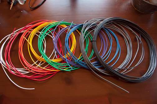 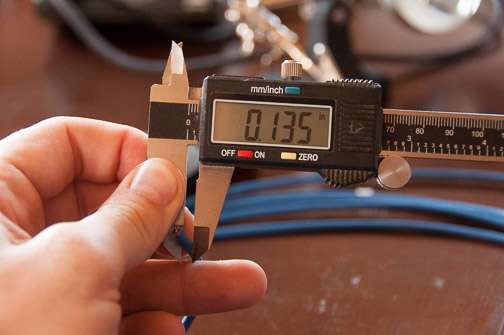 - 1/8" Techflex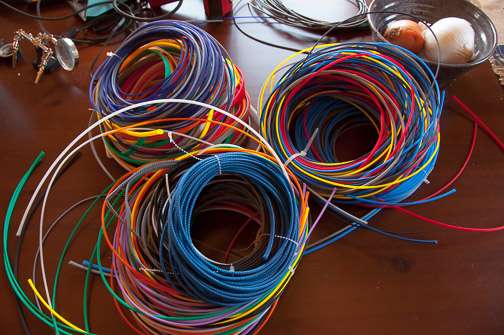 - Monoprice premium RCA Connectors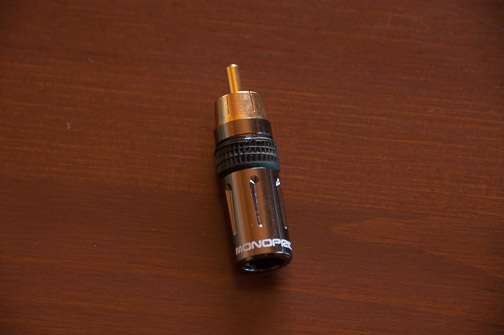 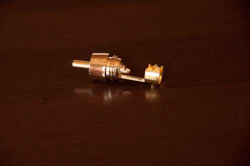 -Heatshrink (basic black 1/4" 1:2 heat shrink works perfectly) 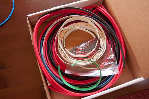 |
|
|
|
Post by trevordj on Mar 3, 2014 17:42:18 GMT -5
The process for making these is surprisingly simple. Once you start making your own RCAs you will wonder why you ever purchased them. Making them yourself provides greater flexibility with installation, allows for more options for colors/labeling, is often higher quality than pre-assembled cables, and is often less expensive. Step 1: Strip about 1/2" of jacket from the Gepco cable. I use a 14 gauge wire stripper tool to easily do this. One mistake I made when I first started assembling these is stripping too much of the jacket. You really only need about 1/2". If you strip too much the strain relief will be unable to clamp down on the jacket. 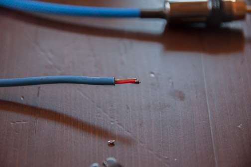 Step 2: In the jacket you will find three wires, two of which are insulated and one that is not. This is in addition to the foil shield that usually comes off with the jacket (the EZ of 61801EZ I believe differentiates that you can easily snap the foil shield for easier assembly of cables. Separate these three wires.  Step 3: Strip about 1/8" of insulation off the positive lead (red) and strip off as much of the negative lead flush with the outer jacket. Twist the negative lead together with the chassis ground. It is important to note that the chassis ground is tied to negative only at the source end. These cables, therefore, become directional. I read a couple white papers that show for an unbalanced source this is superior to other methods for noise rejection (such as leaving the shield disconnected or connecting it at both ends). You will see in a few photos how I just cut the chassis ground off at the other end of the photo. It is also, therefore, important to come up with some way of keeping track of and marking the cable so you can identify which end is which. If you don't want to worry about this (this provides minimal benefit at best), you can just cut the chassis ground at both ends and use the two insulated leads only. 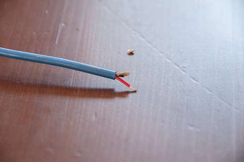 Step 4: Situate the leads in the RCA connector. The red lead attaches to the center pin and the ground + negative attach to the outer ring. 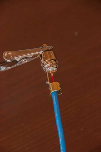 Step 5: Solder the leads to the RCA connector (both the center pin and the outer ring). This isn't intended to be a soldering tutorial so I will just show the final outcome. 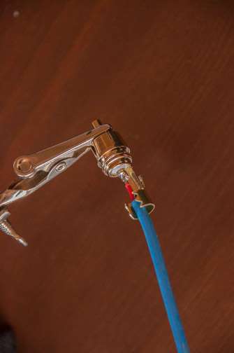 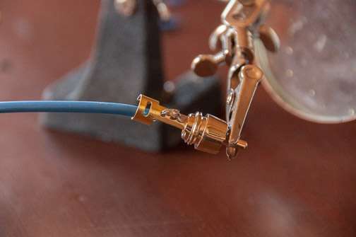 Step 6: Clamp the strain relief to the outer jacket. Note this RCA connector (as most) is intended to be used with a larger diameter coaxial cable so you just have to do the best you can with the strain relief. I am able to get it very tight and secure leaving some slack in the leads to avoid their damage if the cable is pulled. 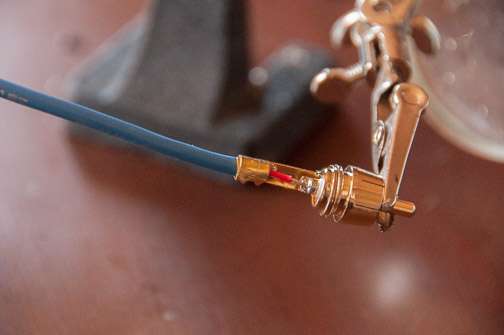 |
|
|
|
Post by trevordj on Mar 3, 2014 17:51:53 GMT -5
Step 7: Cut the cable to length and inch techflex onto the cable. 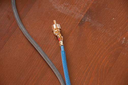 Step 8: Thread two 1.6" pieces of 1/4" heatshrink as well as the RCA connector barrels onto the cable. After the techflex is on it is very important to thread everything onto the cable that will be needed for final assembly. I speak from experience of feeling like an absolute dumbass after soldering the second connector on only to realize I haven't threaded the barrel or heat shrink onto the cable. Double and triple check that everything is on in the right orientation. 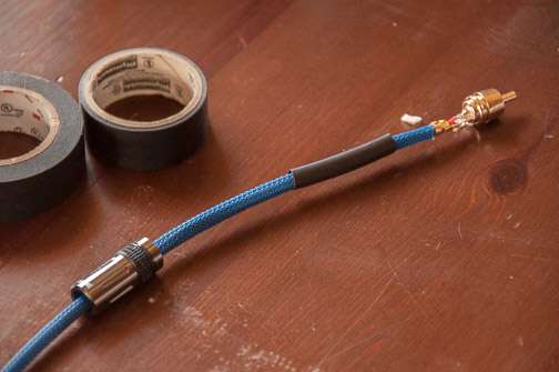 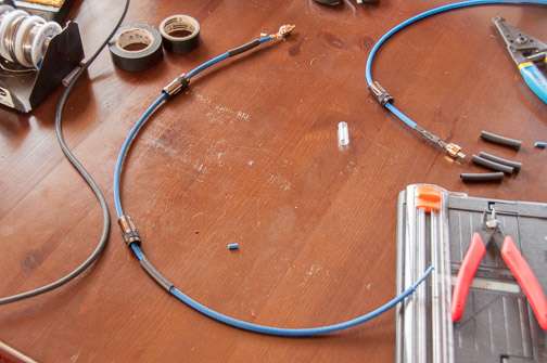 Step 9: Strip and prepare the other end of the cable as above with the exception of cutting the shield (uninsulated) lead flush with the jacket as you will not solder it to the connector at this end. 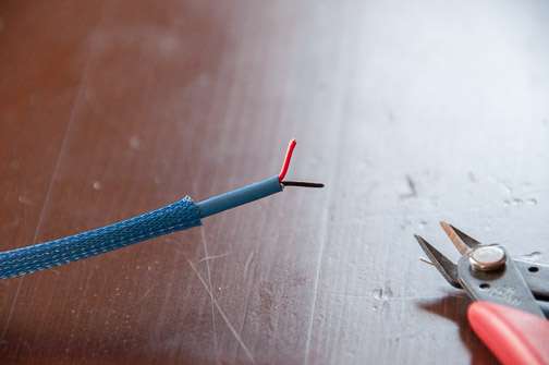  Note I stripped too much of the jacket in this example and didn't strip enough of the negative insulation. Don't take too much of the jacket off and you will avoid having to correct this.   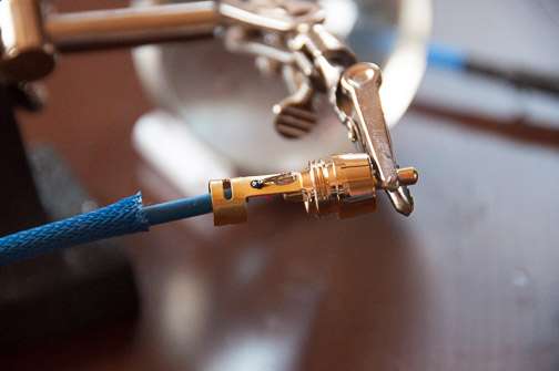 Step 10: Position and shrink the heatshrink after wrapping the end of the techflex with a little electrical tape to hold it in place. 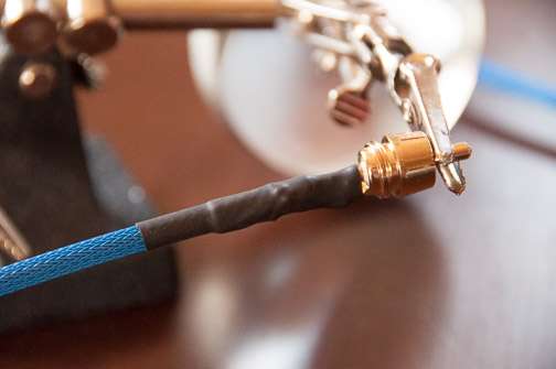 Step 11: Screw the barrel of the RCA connector onto the end. 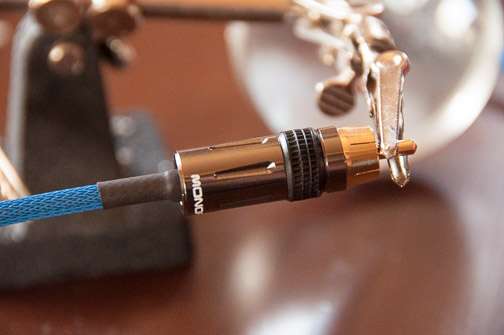 Step 12: Mark the RCA connector where you have chassis ground connected in some way. This will indicate that you need to plug this into the source end for your particular application. I just use a black sharpie and place a mark on the connector to identify it. Step 13: Use black silicone to seal the end of the RCA connector This is probably the part that takes the most time to get used to. This is also an optional step. I do it as it provides a more finished look by sealing the bottom of the RCA connector making for a more professional looking final product (IMHO). Once you get the technique down it isn't bad. I use a syringe filled with black silicone (for easier distribution... you could use it straight out of the tube in your caulking gun but that is a bit unwieldy) to apply silicone around the end of the RCA connector barrel. I try to force the silicone under the barrel in an attempt to get enough purchase with the underside of the connector. Make sure to be careful not to get the black silicone on the techflex as, if you do, it is impossible to get off. Lastly, I use my thumb to work my way around the connector in one motion to smooth the silicone. I then use a paper towel to wipe off any excess silicone on the connector barrel outside or on the far end of the heat shrink. Sometimes you have to go back and forth a couple times smoothing, wiping, and reapplying a bit until you get it right. 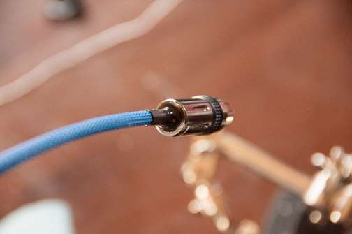 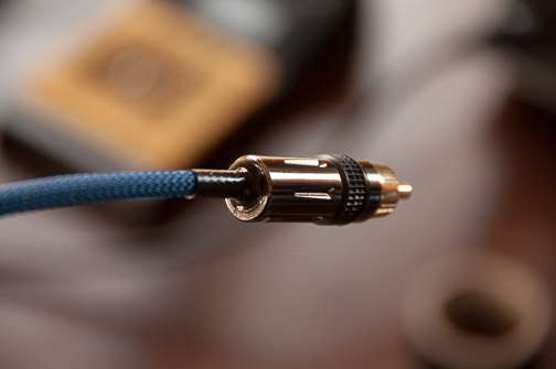 The final product(s) 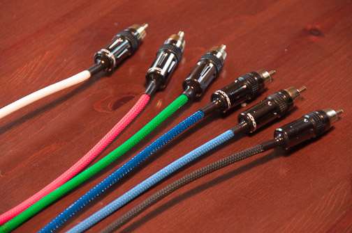 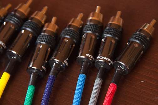 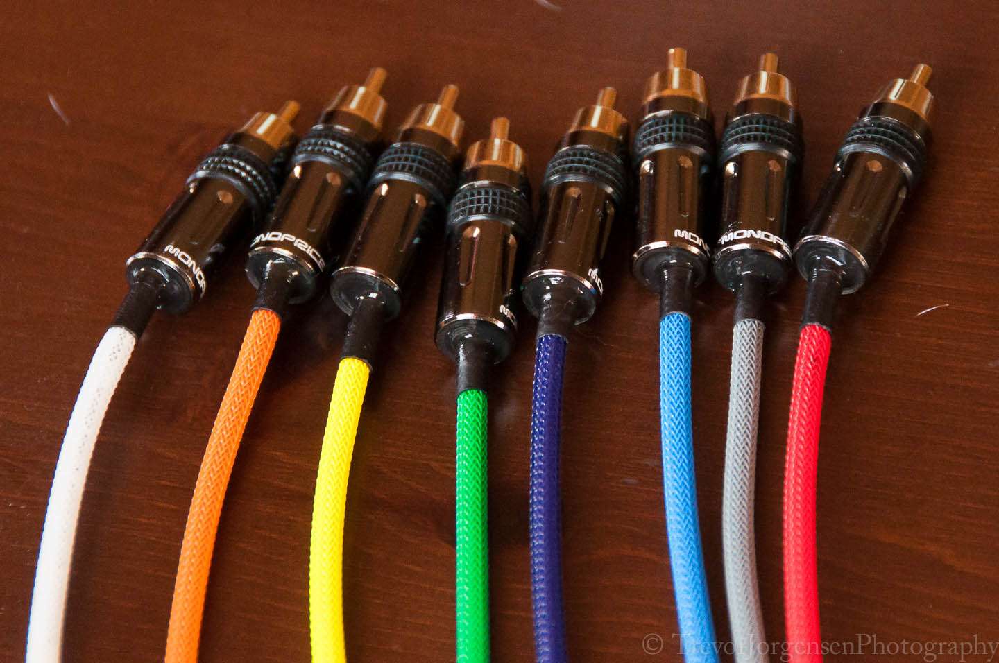 That is it! Thanks for looking and let me know if you need any clarification on the process. |
|
Deleted
Deleted Member
Posts: 0
|
Post by Deleted on Mar 4, 2014 23:46:13 GMT -5
Great tutorial! Cables look great! Have you experimented with different designs/alloys, i.e., braided vs solid core; silver vs silver plated, vs LGC copper. etc? Just curious.
|
|
|
|
Post by dust770 on Mar 5, 2014 2:17:12 GMT -5
Nice tutorial I'll be trying a few of these soon and this will be helpful!
|
|
|
|
Post by trevordj on Mar 5, 2014 21:54:53 GMT -5
Great tutorial! Cables look great! Have you experimented with different designs/alloys, i.e., braided vs solid core; silver vs silver plated, vs LGC copper. etc? Just curious. I have definitely experimented with different cables, Canare and Belden coaxials as well as Canare star quad mic cable in particular. Gepco microphone cable is just so much easier to work with and less expensive. The Canare star quad mic cable is also excellent and has a braided shield unlike the Gepco mic cable. Unfortunately it is 2-3x the price of the Gepco cable, although still an affordable $0.55/foot. I have read some sources showing braided, shielded coaxial cable is superior at RF rejection and ideal for line level interconnects. The sources I looked at didn't compare to mic cable, however (as far as I can recall). From a performance perspective I didn't notice a difference with any of these options as far as fidelity (or noise) was concerned. I imagine this has to do with the relatively short interconnects needed to connect my processor to the amplifiers. However, I have also used the Gepco mic cable for interconnects in a much more electrically noisy environment, e.g. my car. I found this cable to be superior to anything I could buy pre made off the shelf and outstanding in performance (no noise). As far as exotic metals (pure silver, silver plated, silver solder, long-grain copper), I believe those are all marketing gimmicks to sell overpriced cables. In fact, I make my own cables as I want to get maximal performance without all the overpriced hocus-pocus associated with "high end" cables. I will admit some of the high end cables look pretty cool but unless/until I see a measurable difference in reproduction associated with their use I will never purchase them nor will I consider building interconnects with the raw materials used to make them. In my opinion, dollar for dollar, you will never get better performance out of interconnects than if you make them yourself (as long as your soldering skills are decent). I'm not saying my way is the best, but it works for me and I like the way they perform and look. |
|
kr3228
Seeker Of Truth

Posts: 1 
|
Post by kr3228 on Jul 1, 2015 15:27:20 GMT -5
Trevor ; Although your tutorial is over a year old I just came across it
Thanks for posting it , good stuff
I ordered the same Gepco cable you used from Redco and as noted in the tutorial it is well made and EASY to work with.
The shield is manageable and doesn't need to be trimmed down to fit into soldering position.
I do have a question though , when making the IC's can I just use the shield for ground and wrap the red and black insulated wires together for the positive wire ?
|
|
|
|
Post by trevordj on Jul 2, 2015 1:08:06 GMT -5
Trevor ; Although your tutorial is over a year old I just came across it Thanks for posting it , good stuff I ordered the same Gepco cable you used from Redco and as noted in the tutorial it is well made and EASY to work with. The shield is manageable and doesn't need to be trimmed down to fit into soldering position. I do have a question though , when making the IC's can I just use the shield for ground and wrap the red and black insulated wires together for the positive wire ? That is great! I'm glad the tutorial helped you. Definitely post some pictures of your handy work. To answer your question, yes, you could certainly tie red and black together to the center terminal and then use the shield as ground however, this will result in less radio frequency cancelation than the way I posted. I have an article tucked away somewhere that goes over the various connection methods and, for an unbalanced interconnect, tying the shield to ground at the source and and leaving it floating at the component end is better at noise rejection than the method you propose. The second best way would be to tie shield to ground at both ends, the third best is to leave the shield floating at both ends. I am on my ipad now but I will try to find that article ( from Jensen transformers, I think it is called "noise rejection in unbalanced interconnects" or something like that) Honestly rfi is so minimal in home audio and interconnect runs are usually very short so any method will probably work just fine. Now for car audio on the other hand... |
|
|
|
Post by trevordj on Jul 2, 2015 1:10:08 GMT -5
Btw I am getting ready to install a new home theater and I will be building some new interconnects for that system. This time they will be balanced, however as I have a new xpa-7 to play with. When I get them made I will post those here as well.
|
|
|
|
Post by novisnick on Jul 2, 2015 1:16:26 GMT -5
Btw I am getting ready to install a new home theater and I will be building some new interconnects for that system. This time they will be balanced, however as I have a new xpa-7 to play with. When I get them made I will post those here as well. Looking forward to your pics! |
|
|
|
Post by cwmcobra on Jul 2, 2015 8:30:45 GMT -5
Btw I am getting ready to install a new home theater and I will be building some new interconnects for that system. This time they will be balanced, however as I have a new xpa-7 to play with. When I get them made I will post those here as well. Looking forwar to your pics! Same here; keep the info coming! I'll be restarting my home theater project this fall and will enjoy seeing your work on the XLRs. |
|
|
|
Post by lockheed on Jul 8, 2015 9:16:02 GMT -5
Trevor ; Although your tutorial is over a year old I just came across it Thanks for posting it , good stuff I would also like to thank Trevor for his excellent tutorial, it inspired me to make my own cables to connect my new XPA-5 to a Marantz SR 8500 and from My Oppo 103 to the Marantz I'm trying some different components then the ones in the tutorial though.-
Canare L-4E6S Star-Quad Wire Nakamichi 0816E Locking RCA Connectors 1/4" OGRE Techflex
I'm using all black wire and the Ogre techflex for each cable - and will use colored heat shrink for identification
I do have a question for Trevor though You mentioned that you have used the Canare wire before - so just to clarify - since there are 4 conductors I would combine the like 2 for the Signal wire and the ground? - and then combine the 2 wires used for ground and the mesh shielding only at one end? which would be the source end - the Oppo going to the Marantz and the Marantz going to the XPA-5
thanks so much ed
|
|
|
|
Post by trevordj on Jul 8, 2015 9:50:05 GMT -5
Trevor ; Although your tutorial is over a year old I just came across it Thanks for posting it , good stuff I would also like to thank Trevor for his excellent tutorial, it inspired me to make my own cables to connect my new XPA-5 to a Marantz SR 8500 and from My Oppo 103 to the Marantz I'm trying some different components then the ones in the tutorial though.-
Canare L-4E6S Star-Quad Wire Nakamichi 0816E Locking RCA Connectors 1/4" OGRE Techflex
I'm using all black wire and the Ogre techflex for each cable - and will use colored heat shrink for identification
I do have a question for Trevor though You mentioned that you have used the Canare wire before - so just to clarify - since there are 4 conductors I would combine the like 2 for the Signal wire and the ground? - and then combine the 2 wires used for ground and the mesh shielding only at one end? which would be the source end - the Oppo going to the Marantz and the Marantz going to the XPA-5
thanks so much ed
Great choices! The canare star quad mic cable is great stuff. I have always wanted to use the Nak locking RCAs too. I think you will be in good shape with that plan. You are correct regarding the canare cable. I think there are two blue leads and two white leads, tie two of them to the pin and two to the shield. The source end is considered to the the unit that is sending the signal. You have it correct as you posted it. From oppo to marantz source will be oppo. From marantz to xpa-5 source will be marantz. If you tie the shield at the receiving end rather than the source end it will still work just fine just with theoretically decreased noise rejection. Under normal circumstances it probably isn't audible. Iirc listing noise rejection from best to worst: 1) balanced 2) unbalanced, shield grounded at source 3) unbalanced, shield grounded at receiving end 4) unbalanced shield grounded at both ends 5) unbalanced no shield 6) rusty nails taped together and to end. |
|
|
|
Post by lockheed on Jul 8, 2015 10:16:52 GMT -5
Thanks a lot Trevor I'll post some pics - if they're worthy ed |
|
|
|
Post by trevordj on Jul 8, 2015 11:12:07 GMT -5
They will definitely be worthy. Good luck with your cables!
|
|
|
|
Post by trevordj on Oct 4, 2015 23:09:10 GMT -5
Here is my latest iteration of DIY RCAs. These were actually built for my car and they are 100% noise free in that environment (one of the worst). The car audio shop who did my install does very high end builds and was so impressed they have contracted with me to build their RCAs. This makes the investment in the Canare TC-1 crimper and die, Canare 100U stripper for Belden 1505A cable, a techflex hot knife, and Canare RCA connectors well worth it. They certainly are no cheaper than many off the shelf options but the performance is there. I can do these in any color/length. Although for longer lengths I would need to step up to an RG6 cable and a different die. For the record these are a hell of a lot easier to make than the cables I was previously soldering.  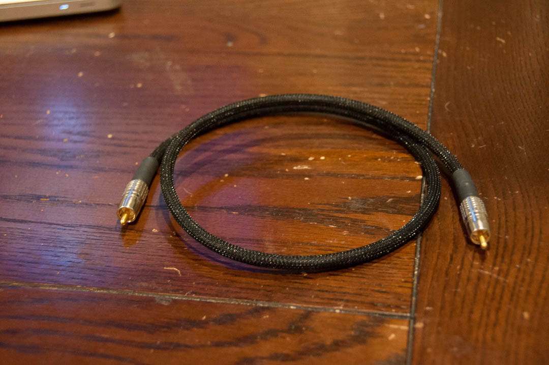 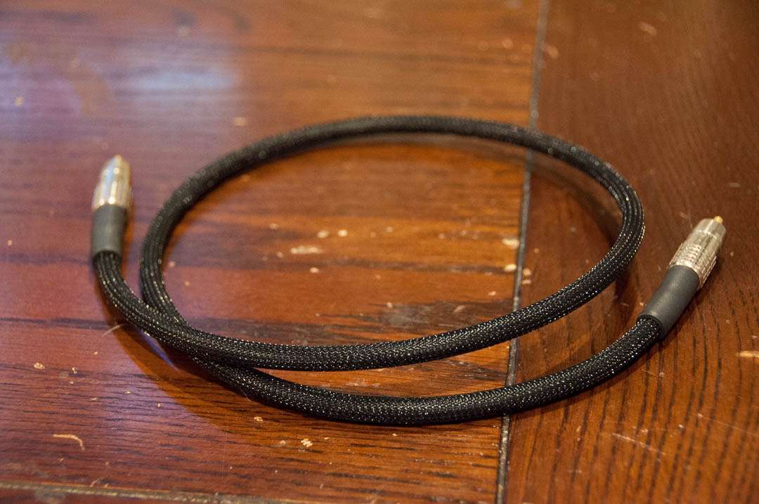 |
|
AudioBear
Minor Hero
  The Only Truth Is Music
Posts: 54 
|
Post by AudioBear on Oct 5, 2015 14:22:41 GMT -5
Here is my latest iteration of DIY RCAs. These were actually built for my car and they are 100% noise free in that environment (one of the worst). The car audio shop who did my install does very high end builds and was so impressed they have contracted with me to build their RCAs. This makes the investment in the Canare TC-1 crimper, die for the RCA, and Canare 100U stripper for Belden 1505A cable and Canare RCA connectors well worth it. They certainly are no cheaper than many off the shelf options but the performance is there. I can do these in any color/length. Although for longer lengths I would need to step up to an RG6 cable and a different die. For the record these are a hell of a lot easier to make than the cables I was previously soldering.    How much for a set of 6 footers? |
|
|
|
Post by vneal on Oct 5, 2015 17:45:40 GMT -5
A fine looking cable
|
|
|
|
Post by trevordj on Oct 5, 2015 18:19:03 GMT -5
How much for a set of 6 footers? Thank you! I just sent you a PM. I don't want this post to come across as spammy (I'm definitely not trying to poach business from Emotiva here) so I will check with the moderators before posting any price information. I am certainly happy to build them for people (not that this is a business for me... I am a physician) but don't want to violate any forum rules. |
|
|
|
Post by teaman on Oct 5, 2015 18:35:43 GMT -5
Nice cables. Feel free to list your cable and pricing in the Emporium. I am several people would be interested!
|
|

