|
|
Post by audiobill on Feb 14, 2020 16:34:39 GMT -5
All, the VTA SP14 preamp is based on the Aikido pre from the tubecad journal KeithL recommends.
|
|
|
|
Post by ttocs on Feb 15, 2020 12:30:32 GMT -5
Most equipment should be designed to operate over a relatively wide range of voltages... because the line voltage itself is subject to significant variation. Power in the US is generally specified at 120 VAC +/-5% (114V - 126V) so equipment designed for use in the USA should be safe to operate over that range. And, to be honest, in most cases there is a lot of leeway around some of the voltages shown on equipment schematics. Ya know, I'm not "always" the brightest kid in the classroom. The voltage is one thing, but really it's gotta be a Current/Impedance issue at hand. The output trans impedance is 2200 ohms, and has 3 taps for 4/8/16 ohms. So if the proper load is attached then the only issue I can see with this is what the tube "expects" to see. As far as I can find, KT88 tubes in an amp of this design wants 4500 ohms Load Resistance, so right off the bat that's double what the output trans is, am I correct with this? (I haven't found the "Tubes made simple for dummies" yet.) . . . . unless it gets into a "it's impedance - not resistance" conversation. Anyway, let's assume that my speakers, generously rated at 4 ohms, are in fact seen mostly as a 2 ohm load, then this cuts the Reflected impedance in half making it 1100 ohms instead of 2200 ohms, and much farther away from what the KT88 would be happy with. Now, moving on to KT120 tubes, all I can find is a mis-stated spec for load resistance (they list it as "Plate Resistance" but it's in the wrong area for this and seems too low for rp) stated as 3000 ohms which is very close to what the OT impedance is. So I'm thinking that since this is a closer match the Current draw coming through the Power Trans is less - or do I have this mixed up? If I'm on the right path then this would be why the PT is running a lot cooler with the KT120. As my high school physics teacher always said, "It's no sin to be ignorant, only to stay that way". edit: Almost forgot to include a visual.  edit: No, it's not a Current issue at all. I'm kinda dumb sometimes. |
|
|
|
Post by ttocs on Feb 19, 2020 0:11:49 GMT -5
Since I packed up the XMC-1 and shipped it off for the Trade-In it's giving me an easy opportunity to check some things during the "down time".
I've learned a few things. The Power Transformers DO NOT heat up due to any problem with excessive loading of any kind. This is me talking to me - "it's the heat soak from the tubes idiot!". While I've been poking around (yes I know about the high voltage, one hand, isolated power) the amps are "sitting" on their transformers with the chassis vertical so the tubes are above the transformers, and ya know what? the transformers don't ever get more than warm except just the side facing the tubes. So this whole time it's just been the hotter running KT88's that've been heating up the power transformers, and why the KT120's which run cooler don't radiate as much heat so the transformers don't absorb as much. Who knew?
So yes, the KT120's run a little more current, a few volts more, and put out about 6-7 watts more (triode mode). This is all good news.
I still say that the 120's are a better match for these amps impedance-wise, unless someone can point out why I'm wrong (again? I don't mind really, I just want to learn).
|
|
|
|
Post by alanhuth on Sept 22, 2020 18:09:16 GMT -5
VTA ST-120 BRAIN TEASER I got a new Bob Latino VTA ST-120 recently (not from Bob). When I received it, the left side was apropriately loud, but the RHS was very quiet. You could hear it, but barely. I talked to Bob and he recommended the chop stick regimen, along with re-soldering any joints that looked odd. No change. Finally, we found something: All the secondary wires on the RHS output transformer measured about 27 ohms to chassis ground (out of circuit) whereas the LHS wires measured around 7 k-ohms. Now, here's the wierd part. When we disconnected the ground from the output speaker post, the amp works perfectly. What is going on? Are there any Sherlock Holmes troubleshooters out there who can surmise what the problem is? Thanks, Alan Sorry the pictures are so big. Any idea why?   |
|
novisnick
EmoPhile
CEO Secret Monoblock Society
Posts: 27,223 
|
Post by novisnick on Sept 22, 2020 19:12:04 GMT -5
VTA ST-120 BRAIN TEASER I got a new Bob Latino VTA ST-120 recently (not from Bob). When I received it, the left side was apropriately loud, but the RHS was very quiet. You could hear it, but barely. I talked to Bob and he recommended the chop stick regimen, along with re-soldering any joints that looked odd. No change. Finally, we found something: All the secondary wires on the RHS output transformer measured about 27 ohms to chassis ground (out of circuit) whereas the LHS wires measured around 7 k-ohms. Now, here's the wierd part. When we disconnected the ground from the output speaker post, the amp works perfectly. What is going on? Are there any Sherlock Holmes troubleshooters out there who can surmise what the problem is? Thanks, Alan Sorry the pictures are so big. Any idea why?   Pictures? 🤔 |
|
|
|
Post by alanhuth on Sept 22, 2020 19:19:07 GMT -5
Are you saying, Where are the pictures? or are you saying Why are those pictures so huge?
If you can't see them, I assume that means that EmotivaLounge blocked them because they were too big. I can see them on my browser, but it's a little embarrassing becase they are so big and I can't figure out how to make them smaller.
|
|
|
|
Post by ttocs on Sept 22, 2020 19:27:48 GMT -5
I don't see any photos. Usually when I post photos they are Attachments. The "Add Attachment" button is above right of the Reply window where you type the response. Once you select the photo on your local computer, you will then need to click on Insert.
|
|
|
|
Post by alanhuth on Sept 22, 2020 19:29:44 GMT -5
That's strange. I'll try it that way. Strange because your quote of my post has huge images copied into it.
OK, I added them as attachments. What I did before was click on the "Insert Image" button on the editor. Some people may see them twice, once large and once small, as I do. Can somebody else verify that for me?
|
|
|
|
Post by ttocs on Sept 22, 2020 19:32:16 GMT -5
VTA ST-120 BRAIN TEASER I got a new Bob Latino VTA ST-120 recently (not from Bob). When I received it, the left side was apropriately loud, but the RHS was very quiet. You could hear it, but barely. I talked to Bob and he recommended the chop stick regimen, along with re-soldering any joints that looked odd. No change. Finally, we found something: All the secondary wires on the RHS output transformer measured about 27 ohms to chassis ground (out of circuit) whereas the LHS wires measured around 7 k-ohms. Now, here's the wierd part. When we disconnected the ground from the output speaker post, the amp works perfectly. What is going on? Are there any Sherlock Holmes troubleshooters out there who can surmise what the problem is? Thanks, Alan Sorry the pictures are so big. Any idea why? 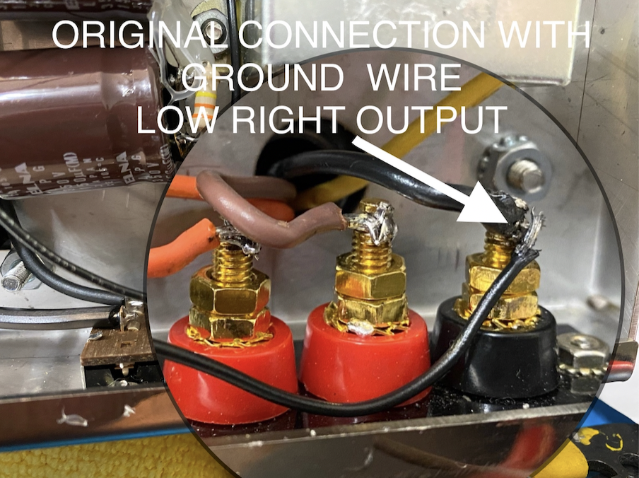 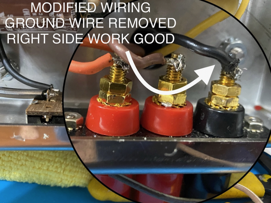 I see the problem with the photos. They need to be converted to jpg. Photos ending with .png don't work. Export the png to jpg which will allow you to also make them more compressed to make them a smaller file size. Friendlier to the Emo server. |
|
|
|
Post by ttocs on Sept 22, 2020 19:35:34 GMT -5
Now that I've Replied, I can now see the photos via the link after I changed to BBCode to view the source.
That black "extra" wire, where does that go?
Is there a companion black wire on the other channel?
|
|
|
|
Post by alanhuth on Sept 22, 2020 19:42:01 GMT -5
The black wire that was removed goes to the ground connector (star ground) screwed to the chassis. There is a matching one on the left side which is still there attached. The right side one was removed and now the amp works. Put that RHS ground wire back, and the right side plays very quietly.
|
|
novisnick
EmoPhile
CEO Secret Monoblock Society
Posts: 27,223
|
Post by novisnick on Sept 22, 2020 19:44:34 GMT -5
Are you saying, Where are the pictures? or are you saying Why are those pictures so huge? If you can't see them, I assume that means that EmotivaLounge blocked them because they were too big. I can see them on my browser, but it's a little embarrassing becase they are so big and I can't figure out how to make them smaller. Missing photos but now I see whats been posted |
|
|
|
Post by ttocs on Sept 22, 2020 19:51:28 GMT -5
The black wire that was removed goes to the ground connector (star ground) screwed to the chassis. There is a matching one on the left side which is still there attached. The right side one was removed and now the amp works. Put that RHS ground wire back, and the right side plays very quietly. I don't have the VTA ST-120, but I do have the Bob Latino M-125. My amps don't have a ground wire attached to the Negative Post for the speaker connection. Something doesn't seem right about this. Do you have the schematic to verify those ground wires are supposed to be connected that way? |
|
|
|
Post by ttocs on Sept 22, 2020 19:55:51 GMT -5
The black wire that was removed goes to the ground connector (star ground) screwed to the chassis. There is a matching one on the left side which is still there attached. The right side one was removed and now the amp works. Put that RHS ground wire back, and the right side plays very quietly. I don't have the VTA ST-120, but I do have the Bob Latino M-125. My amps don't have a ground wire attached to the Negative Post for the speaker connection. Something doesn't seem right about this.Do you have the schematic to verify those ground wires are supposed to be connected that way? Well I found a schematic that shows those ground wires on both channels. So something else is going on. edit: I must amend my previous comment. I looked closer at a photo I took of my amp and there is a ground wire attached to the Negative Speaker Post. |
|
|
|
Post by ttocs on Sept 22, 2020 20:06:01 GMT -5
|
|
|
|
Post by alanhuth on Sept 22, 2020 20:08:47 GMT -5
Yes, I do. I'm not sure that the wiring diagram is public domain. It's the colored one that you must have gotten with your amp also. Well, yes it is. I found it on Bob's website www.tubes4hifi.com/VTA70wiringdiagram3.jpg |
|
|
|
Post by alanhuth on Sept 28, 2020 13:34:52 GMT -5
One idea I got was that when the caps were painted, one might have pinched a wire or scraped off some of the wire coating causing a short in the secondary. Does that make sense based on the behavior we see here?
|
|
|
|
Post by ttocs on Sept 28, 2020 16:16:07 GMT -5
One idea I got was that when the caps were painted, one might have pinched a wire or scraped off some of the wire coating causing a short in the secondary. Does that make sense based on the behavior we see here? I'm not sure what you mean. You say "caps" were painted. Are you referring to the Transformers? Either way, it's simple enough - and recommended - to check the continuity. Safety first! Unplug, wait a long time, check the voltage of all the high voltage items. Use the One-Hand rule. |
|
|
|
Post by alanhuth on Sept 28, 2020 17:29:04 GMT -5
Sorry, yes, the caps on the transformers. I believe that’s what they are called. We already know that there is some contact to chassis ground. Not sure where. Does this explanation make sense? Could a short from the cap result in all 4 wires having the same resistance? 27 ohms.
|
|
|
|
Post by ttocs on Sept 28, 2020 18:41:20 GMT -5
Sorry, yes, the caps on the transformers. I believe that’s what they are called. We already know that there is some contact to chassis ground. Not sure where. Does this explanation make sense? Could a short from the cap result in all 4 wires having the same resistance? 27 ohms. The transformers aren't supposed to be "taken apart" for painting. When I painted mine, I exchanged each screw one at a time with sacrificial screws and nuts during the painting process. The intent is to keep the pressure consistent on the laminations. If the transformers were taken apart then it may have been possible that wires could've been disturbed. Please verify something. You said the Secondary to Chassis measured 27Ω. So you measured the speaker posts with one lead and clipped to the chassis with the other? When I measure the two Positive Posts and the Yellow wire they each measure 0.3Ω, and the Negative Post measures 0.0Ω. My amps are mono so there is no other channel to compare to. Have you verified Chassis to each Primary wire is OPEN? |
|