|
|
Post by hosko on Dec 13, 2016 6:26:49 GMT -5
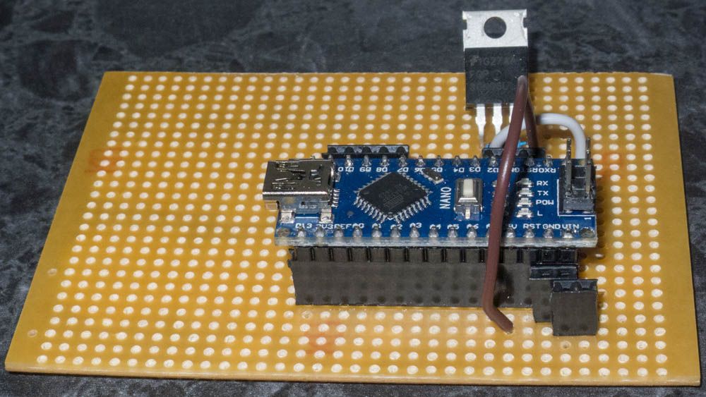
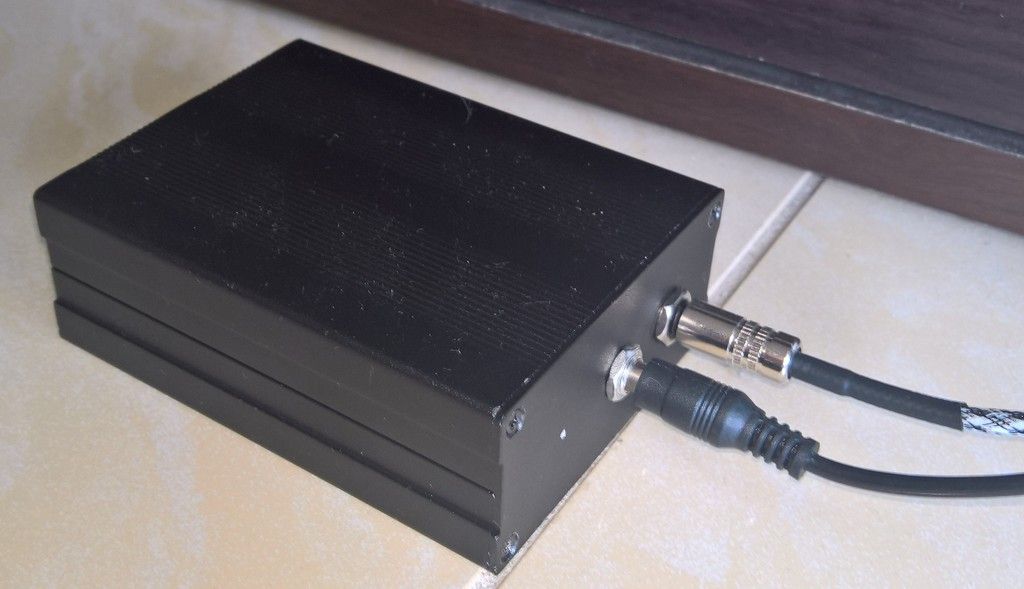
So I want to switch on my XPA200 which is fed from a passive Schiit SYS with my harmony elite remote. Edit - I have completely changed how I want to achieve this, I have switched from using a IR receiver board that had a relay on it to an Arduino based system which will allow it to be upgraded to support more things in the future. Stage one - I will use an Arduino board which will have IR receive capability and a mosfet to drive the 12v trigger. Stage two - design an Arduino shield with POE to power the Arduino, it will have the same as stage 1 but will add a 433mhz RF radio transmitter and RS232. Stage three - Integrate it with OpenHAB on a Raspberry Pi and use MQTT communication between the two. This architecture should allow me to control any home audio equipment. Stage OneHere is the IR to 12v trigger controlling the XPA200 via its 12v input trigger. You can't see me pressing the IR remote but the LED on the breadboard triggers when the one button is pressed, at the same time the mosfet drives 12v to the trigger. When the off command is pushed the LED turns off and the mosfet opens the circuit. Here is a closeup photo of the Arduino Nano on strip board with a FQP30N06L-ND MOSFET to handle switching the 12v trigger   |
|
|
|
Post by geebo on Dec 13, 2016 8:43:40 GMT -5
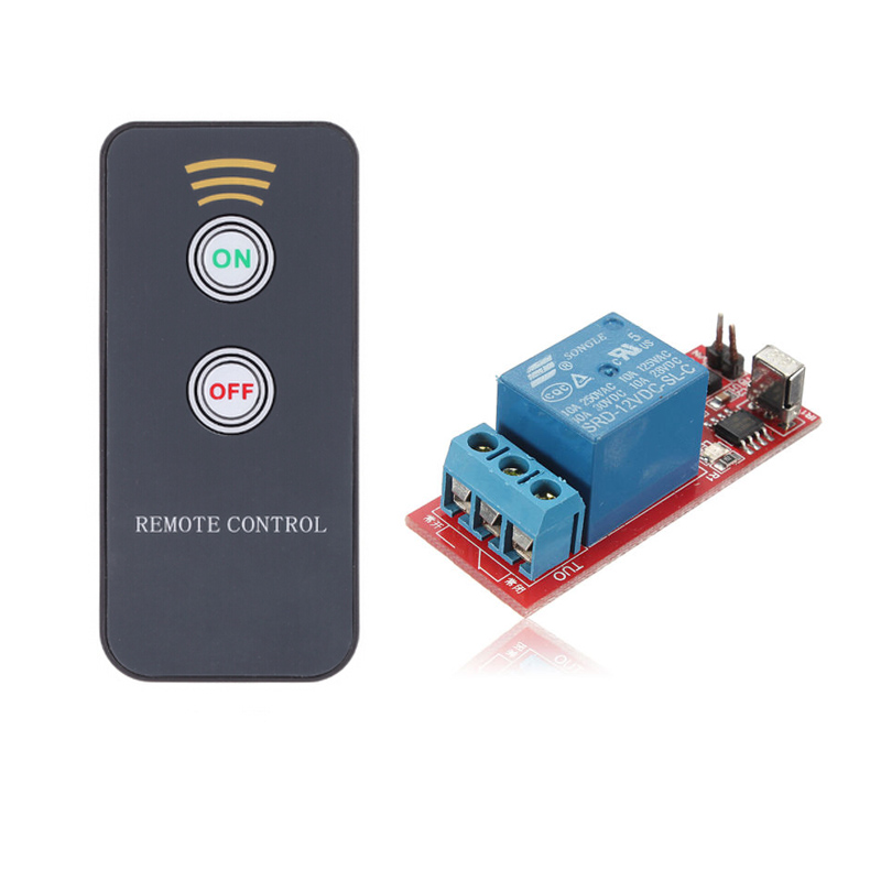
So I want to switch on my XPA200 with my harmony elite remote. So I have purchased a DC 12V Infrared Remote Controllor 1 Channel Relay IR Control Receiver Module it has different on and off buttons which is nice. I am going to put it in a project box and desolder the IR receiver and replace it with a 3.5mm jack so I can plug it into my Harmony hubs IR out. Total cost should be under $20 if I can find a 12v wall wart around the house.  Looks like a nice little project. Be sure to post pics. |
|
|
|
Post by mgbpuff on Dec 13, 2016 9:11:07 GMT -5
Maybe more explaination would help us understand why you would want to do this, because I would think that a preamp trigger out would be a more desirable way to control on-off of an amp. And if the amp is to be controlled directly by this board, why wouldn't you just set a IR mini blaster in front of it instead of modifying it?
|
|
|
|
Post by hosko on Dec 13, 2016 15:48:09 GMT -5
Maybe more explaination would help us understand why you would want to do this, because I would think that a preamp trigger out would be a more desirable way to control on-off of an amp. And if the amp is to be controlled directly by this board, why wouldn't you just set a IR mini blaster in front of it instead of modifying it? My signal chain is DAC with line out > Schiit SYS > XPA200 so there is no way to get a trigger out from anywhere. On the second point, because if it works its a much neater setup, if that fails I will solder the IR receiver back. But it should be straight forward, an IR receiver has 3 pins Voltage, Ground and Out. I only need the Ground and Out. |
|
|
|
Post by mgbpuff on Dec 13, 2016 16:12:29 GMT -5
Interesting, very minimalist, but you still have to push one button.  |
|
|
|
Post by hosko on Dec 13, 2016 16:22:02 GMT -5
Interesting, very minimalist, but you still have to push one button.  as long as it can be done in bed that's not an issue. The play button on the remote already starts playback on the NUC |
|
|
|
Post by hosko on Dec 23, 2016 8:04:11 GMT -5
Well I still haven't received the parts, but I have spent more money. My christmas tree lights are turned on by a rf remote on the 433mhz band that turns a remote power outlet on and off. As I am going to be building a IR to 12v trigger box I might as well make it multipurpose and include an 433mhz transmitter to control the power outlet. I have ordered an Ardunio Pro Mini board, a dual 12v relay and 433mhz tx and rx. I have two weeks off over christmas so this will give me something to do. This project will be useful in the future as the basis of a fan controller in my AV rack.
I shall post pictures as I go.
|
|
|
|
Post by RichGuy on Dec 23, 2016 12:29:14 GMT -5
That looks like a great project! I like to do the same sort of things. All of my HT system is hard wired 3.5 mm IR, controlled by my URC MX-890 remote and an MSC-400 RF base station. All lighting in my home can also be controlled by my MX-890 remote. This is my little IR project box I made as an adapter for controlling my lighting system. I made this to adapt two different 3.5 mm wired IR systems one used a 2 wire mono jack/plug the other used 3 wire stereo jack/plug which were not at all compatible with each other, so this little box makes them compatible so everything works through the MSC-400 to control IR by RF. I can control my system and lighting from anywhere inside or just outside my home by my MX-890 remote (and from pretty much anywhere through my phone).   |
|
|
|
Post by hosko on Jan 15, 2017 22:48:32 GMT -5
Update to the original post with all the changes to this project.
|
|
|
|
Post by leonski on Jan 16, 2017 2:30:42 GMT -5
The good news is you can turn the amp on last, after everthing is on / stable.
Turn it off first, too.
Great project. What does Arduino call the board?
|
|
|
|
Post by hosko on Jan 16, 2017 5:07:03 GMT -5
To begin with I will be using a cheap Nano, I bought 5 for $20. Eventually I will build a shield for something similar to a Freetronics Ten.
|
|
|
|
Post by leonski on Jan 16, 2017 13:40:06 GMT -5
|
|
|
|
Post by hosko on Jan 16, 2017 20:36:58 GMT -5
That board will solely output 4 channels which is ok short term, but if I'm going to the effort I want to make something that I can scale up into a much better solution. Goals would be: IR input 12v Trigger input 12v Trigger output RS232 output It would make more sense to design my own shield (board that plugs into an Arduino) that is designed to control and interface with home audio/video equipment. Well that's the goal anyway. |
|
|
|
Post by leonski on Jan 16, 2017 22:45:34 GMT -5
Hosko,
Please Also Consider adding a TIME DELAY feature to some channels. Having everything slam-on at once is probably not a good idea.
Time delay ON so that it doesn't enable until some time (adjustable) after receiving the on request:
Time delay OFF so that stuff will stay on for a few seconds after receiving the 'off' request.
Amplifiers of an XPR-1 / XPA-1 and some of the X-2 amps grade require lots of uninterrupted current. Some Solid State relays may be what you are looking for in that regard.
|
|
|
|
Post by hosko on Jan 16, 2017 23:24:01 GMT -5
Hosko, Please Also Consider adding a TIME DELAY feature to some channels. Having everything slam-on at once is probably not a good idea. Time delay ON so that it doesn't enable until some time (adjustable) after receiving the on request: Time delay OFF so that stuff will stay on for a few seconds after receiving the 'off' request. Amplifiers of an XPR-1 / XPA-1 and some of the X-2 amps grade require lots of uninterrupted current. Some Solid State relays may be what you are looking for in that regard. Time delay is just a line in code ie delay(2000); will put a 2 second delay in. |
|
|
|
Post by leonski on Jan 16, 2017 23:55:23 GMT -5
If running the highest powered amps, I'd ONLY try to make sure the relay will handle the current. Turn-On Surge for a big amp with no slow-start feature can be pretty large and if the relay is
right at the edge, you MIGHT fuse contacts. In the Old Days, my toolbox included a special file set for relay contacts! All relays were of course, socketed, so replacement was quick and painless.
Love software programability. Old-School TD relays had additional circuitry and a 'knob' to control time.
|
|
|
|
Post by hosko on Jan 23, 2017 2:30:03 GMT -5
Original post updated with a video of the breadboard running.
|
|
|
|
Post by leonski on Jan 23, 2017 18:55:06 GMT -5
Good Job. For low current stuff, a fairly easy DIY.
Are there available boards or does everyone need to breadboard it? How much current are the relays good for? SS or 'mechanical' relays?
Can you publish entire schematic?
I'd like to see an INSERTABLE time delay using the 12v trigger standard. Install between a preamp and the amp to DELAY the amp startup by just a few seconds.
I think such could be done without stressing the current capacity OF the preamp.
|
|
|
|
Post by hosko on Jan 24, 2017 1:48:34 GMT -5
Good Job. For low current stuff, a fairly easy DIY. Are there available boards or does everyone need to breadboard it? How much current are the relays good for? SS or 'mechanical' relays? Can you publish entire schematic? I'd like to see an INSERTABLE time delay using the 12v trigger standard. Install between a preamp and the amp to DELAY the amp startup by just a few seconds. I think such could be done without stressing the current capacity OF the preamp. Its on the breadboard as part of the prototyping process, from there it gets put onto a strip board for more testing. My wife asked the same thing, she wasn't impressed we all the cables.  From here I will keep adding on elements like IR input, RS232 output etc I'm currently using an Arduino Nano which supports 5-12v input, this makes the circuit super easy. The 12v input in parallel goes to the Arduino and + output of the trigger. A digital programable output pin goes to the Gate of the N-Channel MOSFET, Ground goes to the Source pin and the Drain pin goes to the - output of the trigger. When the Gate is driven HIGH the the mosfet sends the Source to the Drain and the trigger circuit is closed, when the gate goes LOW the mosfet opens the circuit between the two. So its a simple electronic switch. You could use a relay however I like recycling circuits so the mosfet supports PWM so it could be used to also drive PWM fans or LEDS. The FQP30N06L-ND MOSFET supports up to 60V 32A so its very handy. |
|

